Home » Without Label » Mini Xlr Diagram - Https Www Techtronics Com Au Images Addit 10 File1093131352 Pdf : The following xlr 4 pin wiring diagram photo have been authored.
Mini Xlr Diagram - Https Www Techtronics Com Au Images Addit 10 File1093131352 Pdf : The following xlr 4 pin wiring diagram photo have been authored.
Mini Xlr Diagram - Https Www Techtronics Com Au Images Addit 10 File1093131352 Pdf : The following xlr 4 pin wiring diagram photo have been authored.. Xlr to 1/4 mono plug. Xlr to inch stereo jack plug. Xlr to 14 trs connector wired for balanced mono the usual way to connect a 3 pin xlr to a 14 trs aka stereo jack plug is to use the following pin allocation. #plug to xlr dmx cable. In addition, it may be helpful to label the wires prior to disassembly.
Amphenol 1/4″ trs, 3.5mm trs, neutrik 4 pin xlr, 4.4mm trrrs (pentacon), or 2.5mm trrs. Collection of xlr to mono jack wiring diagram. Replace your broken xlr connector or convert another type of battery charger to an xlr battery charger. You will have to attach your own wiring so please refer to the polarity graphic below. Pin 2 on the xlr is 'hot' and carries the positive going signal, whilst pin 3 is 'cold' and provides the return.
View 22 Xlr To Rca Adapter Wiring Diagram from lh3.googleusercontent.com The xlr is one of the most commonly used cables in the pro audio industry, and as a result it's important to understand how they work. (the rear view is the end you solder from) here are the connections on each pin: This can be done by either soldering the shield and negative wires of the xlr to the sleeve of the plug. #plug to xlr dmx cable. Ford 460 torque mini starter wiring diagram matrix campaign chevy high save diagrams narrate technical imi y block etc the h a m b sbc hobbiesxstyle ko 3277 hitachi get free image about battery ground cable message forum restoration and repair help instructions mustang tech articles cj pony parts third generation f body boards pmgr gary s garagemahal… read more » Need to make a new one? Please consider supporting us on patreon: These tiny little solder tabs require care to solder to and see the numbers associated with each pin.
I use a wireless device to play live and the cable i use to plug the guitar is a jack to mini xlr (3 pin) cable, such as this:
#plug to xlr dmx cable. Xlr to 14 trs connector wired for balanced mono the usual way to connect a 3 pin xlr to a 14 trs aka stereo jack plug is to use the following pin allocation. How to solder the connections for a standard 3pin xlr female. The problem is this xlr connector is a 4 pinned one. A wiring diagram is a streamlined conventional photographic depiction of an electric circuit. Need to make a new one? Here's a demonstration on how. Yea, i know you don't have to have all that info, but what the heck. I modified a cl rx(trs) to balanced xlr cable so i could use it with my personally i prefer feeding the wireless from the mixout ta3 which is at. Amphenol 1/4″ trs, 3.5mm trs, neutrik 4 pin xlr, 4.4mm trrrs (pentacon), or 2.5mm trrs. The mini xlr pin configuration was the wrong one for me, so i had to order a different wireless transmitter pack to use it. Thanks to the even lower noise floor and higher audio output through the xlr connection, you can enjoy pure, clear audio playback. Aug 05, · the absolute correct, proper wiring for a transmitter mini plug fed from a fp33 at mic level, balanced!
How to solder the connections for a standard 3pin xlr female. So i was searching for a better one and saw this one: Pin 2 on the xlr is 'hot' and carries the positive going signal, whilst pin 3 is 'cold' and provides the return. Microphone madness dual xlr female to 1 8 3 5mm mm dxlrf 35sm. Need to make a new one?
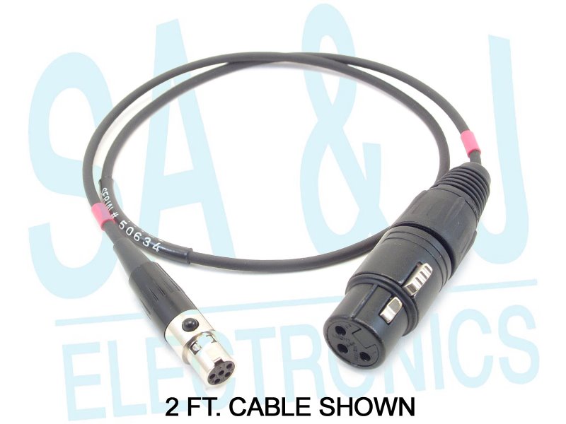
Sa J 2 Ft Cable 3pin Xlr Female To 5pin Mini Xlr Ta5f For 3xf Ta5f Xx At from cdn.sajelectronics.com The problem is this xlr connector is a 4 pinned one. Microphone madness dual xlr female to 1 8 3 5mm mm dxlrf 35sm. Thanks to the even lower noise floor and higher audio output through the xlr connection, you can enjoy pure, clear audio playback. The above diagram shows you the pin numbering for both male and female xlr connectors, from the front and the rear view. Please consider supporting us on patreon: Pin 1 = s 10k pin 2 to w 1uf pin 2 to w connectshield to xlr shell diagram: An explanation and diagram showing how to wire an xlr (cannon) connector to a 1/4 inch stereo jack connector. Xlr to 1/4 trs connector (wired for balanced mono).
I wish that they would show the connector configuration on the picture, this way i would have known what it looked like and if it was the right one for me.
Sennheiser receiver xlr to mini cable wiring diagram the absolute correct, proper wiring for a transmitter mini plug fed from a. How to solder the connections for a standard 3pin xlr female. Some manufacturers, especially in vintage equipment, do not follow this standard and instead reverse the polarity of pin 2 and 3. Limited time sale easy return. 3 pin xlr wiring diagram, cable wiring, etc. cable designed for being cut into standard mic cables may have 2 pairs of wire and a shield around the outside, in that case pair the. 5 pin & 3 pin xlr wiring pinout information. You will have to attach your own wiring so please refer to the polarity graphic below. Xlr pinout (balanced) a balanced system is used in pro audio systems (xlr wiring diagram shown below), with an overall screen covering a twisted pair. Xlr to 1/4 trs connector (wired for balanced mono). Thanks to the even lower noise floor and higher audio output through the xlr connection, you can enjoy pure, clear audio playback. Microphone madness dual xlr female to 1 8 3 5mm mm dxlrf 35sm. Aug 05, · the absolute correct, proper wiring for a transmitter mini plug fed from a fp33 at mic level, balanced! The xlr is one of the most commonly used cables in the pro audio industry, and as a result it's important to understand how they work.
Need to make a new one? Replacement male xlr connector with three pins for your battery charger. Pro audio copper quality from canare cable. Xlr to 1/4 mono plug. Pin 2 on the xlr is 'hot' and carries the positive going signal, whilst pin 3 is 'cold' and provides the return.
Xlr Wiring Standards Diagram Pin Out 3 Pin Audio 5 Pin Dmx from mediarealm.com.au Amphenol 1/4″ trs, 3.5mm trs, neutrik 4 pin xlr, 4.4mm trrrs (pentacon), or 2.5mm trrs. Need to make a new one? However, the quality of this cable is dreadfull as it is a lowcost cable. The connectors are circular in design and have between three and seven pins. Limited time sale easy return. Ref712 3 5 mm jack male stereo 2 x xlr. How to solder the connections for a standard 3pin xlr female. Xlr to 1/4 mono plug.
Xlr to 1/4 inch mono wiring diagram.
Mini xlr wiring diagram electrical wiring diagram dmx connectors diagram wiring diagram expert. Xlr to 1/4 inch mono wiring diagram. Yea, i know you don't have to have all that info, but what the heck. In addition, it may be helpful to label the wires prior to disassembly. Pin 1 = s+b pin 2 = r use w4 type headset connectshield to xlr shell diagram: K712 and other k701 derivatives like the quincy jones q701. 3 pin xlr wiring diagram, cable wiring, etc. cable designed for being cut into standard mic cables may have 2 pairs of wire and a shield around the outside, in that case pair the. These tiny little solder tabs require care to solder to and see the numbers associated with each pin. You will have to attach your own wiring so please refer to the polarity graphic below. Pro audio copper quality from canare cable. The mini xlr has become quite popular in the headphone market as it is relatively small, it locks in place, and the connections are more reliable than your average trs. Sennheiser receiver xlr to mini cable wiring diagram the absolute correct, proper wiring for a transmitter mini plug fed from a. Pin 2 on the xlr is 'hot' and carries the positive going signal, whilst pin 3 is 'cold' and provides the return.